simulate
Picasso’s simulation module (Picasso: Simulate) is a tool for evaluating experimental conditions for DNA-PAINT and generating ground-truth data for test purposes. This allows systematic analysis of how different experimental parameters such as imager concentration, target density or integration time influence the imaging quality and whether the target structure can be resolved with DNA-PAINT.
By default, Picasso: Simulate starts with preset parameters that are typical for a DNA-PAINT experiment. Thus, meaningful raw DNA-PAINT data can be readily simulated for a given input structure without the need of a super-resolution microscope. The simulation output is a movie file in .raw format, as it would be generated during an in vitro DNA-PAINT experiment on a microscope.
Simulate DNA-PAINT image acquistions
Start
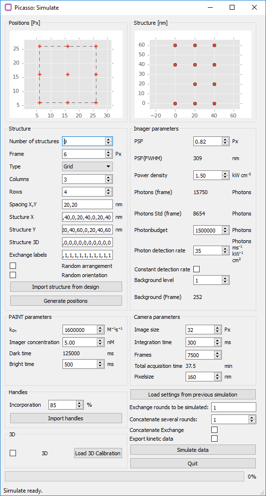
Picasso: Simulate.Define the number and type of structures that should be simulated in the group
Structure. Predefined grid- and circle-like structures can be readily defined by their number of columns and rows, or their diameter and the number of handles, respectively. Alternatively, a custom structure can be defined in an arbitrary coordinate system. To do so, enter comma-separated coordinates intoStructure XandStructure Y. The unit of length of the respective axes can be changed by setting the spacing inSpacing X, Y. For each coordinate point, an identifier for the docking site sequence needs to be set inExchange labelsas a comma-separated list. Correctly defined points will be updated live in theStructure [nm]window. Note that entries with missing x coordinate, y coordinate or exchange label will be disregarded. When a structure has been previously designed withPicasso: Design, it can be imported withImport structure from design. A probability for the presence of a handle can be set withIncorporation. By default, all structures are arranged on a grid with boundaries defined byImage sizeinCamera parametersand theFrameparameter in theStructuregroup.Random arrangementdistributes the structures randomly within that area, whereasRandom orientationrotates the structures randomly. Selecting the buttonGenerate positionswill generate a list of positions with the current settings and update the preview panels. A preview of the arrangement of all structures is shown inPositions [Px], whereas an individual structure is shown inStructure [nm].The group
PAINT Parametersallows adjustment of the duty cycle of the DNA-PAINT imaging system. The mean dark time is calculated by τd = 1/(kon·c). The mean ON time in a DNA-PAINT system is dependent on the DNA duplex properties. For typical 7-bp imager strands, the ON time is ~200-300 ms.In
Imager Parameters, fluorophore characteristics such as PSF width and photon budget can be set. Adjusting thePower densityfield affects the simulation analogously to changing the laser power in an experiment.The
Camera parametersgroup allows the user to set the number of acquisition frames and integration time. The default image size is set to 32 pixels. As the computation time increases considerably with image size, it is recommended to simulate only a subset of the actual camera field of view.Select
Simulate datato start the simulation. The simulation will begin by calculating the photons for each handle site of every structure and then converting it to a movie that will be saved as a .raw file, ready for subsequent localization. All simulation settings are saved and can be loaded at a later time withLoad from previous simulation.(Optional step for multiplexing) Multiplexed Exchange-PAINT data can be simulated by adjusting the
Exchange Labelssetting. For each handle in the custom coordinate system (Structure X,Structure Y), an Exchange round can be specified. The different imaging rounds can be visually identified by color in theStructure [nm]figure. For each round, a new movie file will be generated. By default, the simulation software detects the number of exchange rounds based on the structure definition and will simulate all multiplexing rounds with the same imaging parameters. It is possible to have different imaging parameters for each round, e.g. when using image s with different ON-times. To do so, one can simulate multiplexing rounds individually. In theExchange rounds to be simulatedfield, enter only the rounds that should be simulated with the current set of parameters. Change the set parameters and the multiplexing round and simulate the next data sets. Repeat until all multiplexing rounds are simulated.